2/13/2012

Accessing parameters through Revit API


Introduction

Part 1 of this project involved the use of Revit API to overcome some issues faced during the project 1 which could not be overcome otherwise. While for part 2, API code was used to arrive at some creative and interesting results.

Part 1

During the project 1, the mass family that was developed initially comprised of all the building elements. However, when the family was transferred to the project, Revit was unable to create mass floors. Hence the family was edited into two separate families called CORE (having building mass and central core) and SPINE (having outer spine). Both the families had the same underlying skeleton of reference line, reference points and parameters. The problem being that the user now had to enter the parameter values separately for both the families. This part aimed at resolving this issue through API code.
Figure below shows the underlying logic of API code.


Following figures show some snippets of code


Retrieve family instances and their parameters


Get the values of parameters


Update the value of SPINE family parameter

Before running the code 


After running the code


Part 2

The second part of the project 2 aimed at exploring the creative ways in which Revit API can be used. The aim was to change the material of window family in a random fashion while the width of the window is determined by the elevation at which it’s located. Initially it was intended to apply the window family (Curtain panel pattern based) on the surface of original building, but Revit was unable to generate the geometry. Hence the concept was tested on a mass family with flat surfaces. 
Figure below shows the underlying logic of API code.


Following figures show some snippets of code


Get the values of elevation


Retrieve family instances and their parameters


Get the values of parameters


Update the value of family parameter


Before running the code


After running the code


>>>In Progress<<<

11/09/2011

Parametric Building Model

The task was to create a Building Information Model and a Parametric Design for a selected case study. For my case study I selected HSB Turning Torso designed by Santiago Calatrava, an eminent Spanish architect. The project is located at Malmo, Sweden and is recognized as the tallest residential tower in EU. The construction was completed in 2006. More details about the project can be found at http://www.calatrava.com/


(Source: http://es.wikiarquitectura.com)
Creating a Building Information Model:
Information Collection
Before initiating the 3D modeling, the first step was to gather as much information about the building as possible. Most important among those were plans, details, 3d models and pictures/videos. Being a recently completed and renowned building, its widely documented. Hence the information gathering was not difficult. (The sources that were used in this project have been mentioned in the reference section)


Creating Mass Family
There are three major elements to be modeled as mass

Concrete Floor Mass 
As a whole, the building was composed of a single floor profile rotated by 90 degrees clockwise from bottom to top. Angle between each floor was 1.6 degrees. 5 Floors were combined to form a cube and there were 9 cubes in total forming the building. Angle between each of these cubes was 10 degrees and they were separated by one floor (open to outside). There are total of 57 floors in this building.

Concrete Core (Shear Wall)
A cylindrical concrete core runs through the building and it encloses lifts, staircases and major services. The thickness of the core reduces from 2.5 m at bottom to 2 m at top. 

Steel Spine
A steel spine runs on the outside serving as a mechanism to transfer lateral load. The path followed by spine is same as floors.

Most important requirement of the project was that the mass had to be parametric. That is, one should be able to control and modify critical building dimensions. Besides, some assumptions have been made while modeling in order to meet the requirements within given time frame.

Assumptions made:
Even though the lower cuboid has 3 extra floors (to accommodate for common areas like lobby etc. of the building), all of the cuboids have been assumed to have equal height dimensions and have 5 floors each. Each of these cuboid is followed by a common open area having a height same as floor height. 
Even though the thickness of core decreases as we go up, this project assumes it to be constant throughout.
Elements of bracing have been modeled as cylindrical (original project has cigar shaped elements). There are small bracing at each floor level. To avoid the complexity these floor elements have not been modeled.
Lets get started.

Floor Mass:
CAD plan was worked out using the floor plan image. The plan was imported into Revit conceptual mass family. The profile was traced at Level 0 and Level 1 (197 m above). The Level 1 profile was rotated 90 degree clockwise. Create form command did not result in desire profile.Whenever using top and base profile to create a sweep, Revit always considered sweeping the nearest edges. 
The solution lied in creating the profiles at all level without any rotation and somehow driving the angle between them through a parameter.
The modeling approach is shown through figures below.
10 levels were created and linked through related height parameters. They are named from L1 through L10

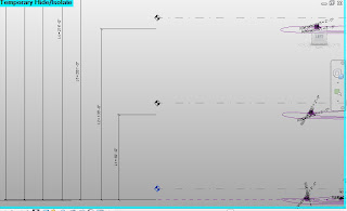
Level and Height Parameters
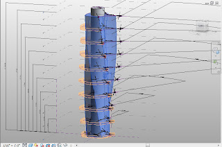
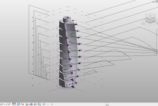
A reference line was drawn on level one work plane. The idea was to draw a geometry on the work plane of this reference line, so that the form can be driven by the line. Later the reference line was given angle parameter in order to control its rotation. This process was repeated for every step. The angles assigned to reference lines at each level were interlinked using formula. The outline of building floor was drawn as reference line (using model lines at this stage results in form not being updated automatically). Selecting the outlines at each level, the building form was generated.


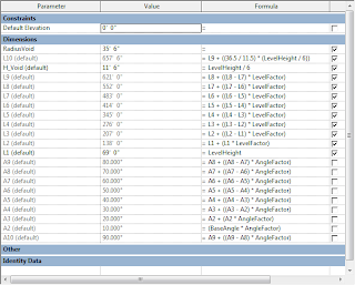
Dependent Parameters in Conceptual Mass Family
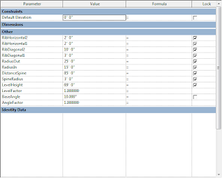
User Controlled Parameters in Conceptual Mass Family
NOTE:
L1 through L10 - Control Level heights (L1 the lowest and L10 being highest)
A2 through A10 - Control Angle of main reference line at each level from level 2 through level 10
User Controlled
LevelHeight - Controls height between each level
LevelFactor - Controls ratio of height between each level
BaseAngle - Controls angle difference between each level
AngleFactor - Controls ratio of angle difference between each level
DistanceSpine - Controls location of spine wrt main building
SpineRadius - Controls dimension of spine
RadiusIn - Radius of inner circle for the shaft
RadiusOut - Radius of outer circle of shaft
RibHorizontal1 - Radius of rib on building side
RibHorizontal2 - Radius of rib on spine side
RibDiagonal1 - Radius of diagonal rib on building side
RibDiagonal2 - radius of diagonal rib on spine side
RadiusVoid - Inner radius of the void that cuts main building at each level


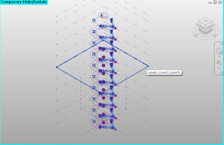
Building Profile (made of reference lines) copied at different levels
To create the open spaces after each cuboid, voids were used. The void geometry was also related to the reference lines and the height was linked to the level heights through formula.

Voids at different levels
Void Profile (also made of reference lines) at different levels
Central Shaft:
Central shaft was made of concentric circles at level 1 and level 10 (topmost level). The circles were also associated to the main reference lines at those levels. Inner circles were used to create a void which cut the solid form created by outer circles.

Central Shaft (made of two concentric circle)

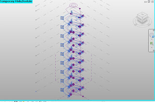
Different Geometrical Elements in Family

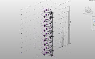
Family seen with major parameters
Spine:
Spine was the most challenging part of the project. Intention was to model a spine element whose radius as well as distance form the main building could be controlled. Modeling the circular shapes at each level and then creating a form with them was a solution but it could not be changed. Since it had to move along with the building profile at each level, its distance could not be referred to the vertical planes. The issue was resolved by introducing two reference points - one at building center and another at circles center. These two points were then dimensioned.


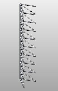
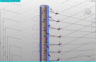
Spine with horizontal and diagonal ribs

Spine seen with driving parameters


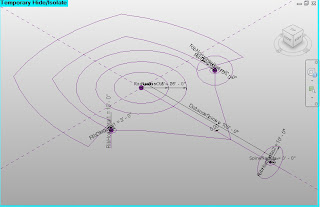
Major drivers of Geometry (with associated parameters)
The ribs were of two kinds:
Horizontal ones were modeled through reference circles hosted by reference points present at the ends.
For diagonal ribs even though complexity was observed initially (since the length will change if the rotation of levels is changes), the issue was resolved by reference circles hosted by points at each end (similar to horizontal ribs).

Creating Curtain Family:


The project has two types of windows applied on facade. There are rectangular windows and circular elements at the edges where ribs meet the building. Both were modeled in a similar fashion. Rectangular "curtain panel pattern based" was used as base template. Reference rectangle (or circle) was made with center point being host. The required geometry was achieved through two solids (for wall and glass pane) and a void (to create opening in wall). The parameters of reference line and solids was controlled to achieve a flexible family where wall thickness, glass thickness and window dimension could be altered.
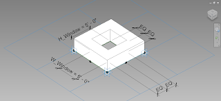
Square Curtain Panel
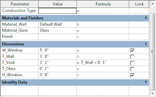
User Controlled parameter in Square Curtain Family
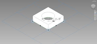
Circular Curtain Panel Family
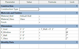
User Controlled parameters of Circular curtain panel family
NOTE:
T_Wall - Thickness of surrounding mass
T_Glass - Thickness of glass panel
T_Void - Thickness of void cutting the outer mass
W_Window - Window width
H_Window - Window height
R_Window - Radius of circular window
Material_Wall - Wall material
Material_Glass - Glass material

Project Level:


All of these families were imported at project level. Levels were drawn for each floor and mass floors were created afterwards. Floor roof and walls were applied to different surface. Floor 2 was detailed to give a sense of space use.


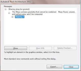
The major limitations observed were:

  1. Revit does not identify floors within complex families. For this project, when the main structure was imported to project along with the spine, Revit was unable to generate mass floors.  
  2. Speed slows down drastically while dealing with complex families at project level.
  3. Moreover, while creating the curtain family, void size had to be more than (and not equal to) the solid it cuts. If its equal, Revit assumes a surface in the place even when the design intent was not so.


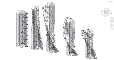
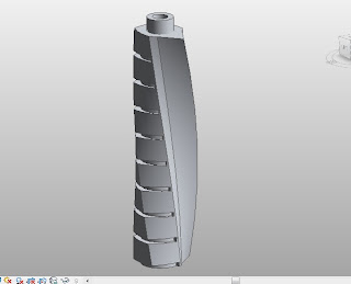
Playing with the parameters


References:

2/15/2011

Nucleus is here !!!

Recently nucleus plugin for Revit was launched and Vasari 1.1 released today also has this functionality. Details can be found at http://labs.autodesk.com/utilities/nucleus/
It adds an immensely powerful functionality in Revit which will prove to be very useful in early design stage- when architects try to find the form. Fairly complex geometries can be created with this tool, which was earlier limited to Maya only.
I will try to play with some of the options available. In the meantime, few useful videos are available at the link posted above.

1/02/2011

From Beginning to End-4D BIM for COSC 650

The Assignment was to arrive at 4D BIM for "The Church of Jesus Christ of Latter Day Saints at College Station, TX", which could then be used for visualization, construction sequencing, clash detection, site logistics etc. Overall, the project was broken into three stages:

Development of
1) 3D BIM
2) 4D BIM (attaching model with schedule)
3) Video

Stage 1: Development of 3D BIM


Extracting Information From CAD
  • Plans (.dwf) and Specification (.pdf) for the building were provided by the instructor.
  • First task was to eliminate extraneous information from the drawings so that they could be used in Revit for reference purpose easily (even though layers can be managed in Revit, pertaining to large number of layers involved I chose to extract the information in AutoCAD first and then import in Revit). For this .dwf was converted to .dwg using free converter available on internet. Once .dwg files were in hand, their units were adjusted and drawings manipulated to extract useful information (geometry and dimension) for creating model.
  • Once .dwg were ready, it was time to import them in Revit and build upon them.
File SetUp
  • Two models were created - One for architecture and structural part combined, and the Second for MEP. Using shared coordinates they were tied together (so that they fit snugly). Part of Architecture model was developed first to set the grid lines and other major references (walls) for MEP model. This model was linked with the MEP model. Copy and Monitor tools were used in the course of project to ensure model integrity at all times.
  • Revit file was setup using the default construction template_imperial. Important levels were assigned and the naming convention was chosen to reflect the original drawing. 
  • .dwg file was imported and grid line was drawn accordingly. 
Model Development
  • Model was developed in the order of Foundation > Walls > Windows & Doors > Truss & Rafters > Roof Covering > Steeple > Fascia and other decorative elements. The corresponding plans and elevations/sections were imported as and when required.
  • Existing wall types were modified into the required wall types. There were approximately 20 different wall types.
  • Window, door and column families were created separately.
  • Truss family were modified in Revit structure and then used.
  • Fascia and Steeple were made as component family but with fixed dimensions.
  • The Rostrum platform was created as an in-place family.

Stage 2: Development of 4D BIM


Activity based schedule to Deliverable based schedule
Before the model could be exported as .nwc files, the schedule had to be developed and the Revit model to be reworked upon. The construction schedule for the project was provided by the instructor but the problem was that it was activity based. For the schedule to be attached to model, it was converted to deliverable based schedule.
The approach used is explained below:
All the activities required for a particular deliverable were listed. For example, for walls, the activities ranged from erection of studs to painting. The activities available in the schedule, their sequence and the detail in the model decided which activities can be consolidated to yield a particular model element. Many reasonable and intelligent assumptions were made from time to time as well. The sequence of activities was modified to reflect the changes.

Reworking the Revit Model
Once the quantity of deliverable and the duration required to achieve that was known, that particular element was reworked to reflect the deliverable available for a single day ( For example, If roof covering is going to take 8 days then roof covering element was divided in 8 equal parts - so that each of those parts can be tied to a single day roof covering deliverable. The process was repeated for all the model elements.)

Exporting as .nwc file
Once the model and schedule was in place it was the time to export as .nwc files. To save time in Navisworks later, the elements were exported one by one (based on single day deliverable). While exporting from a particular view only the elements visible in the view are exported as .nwc. This feature proved to be very useful. The required elements were easily separated from rest of the model using hide tab in Revit. The exported .nwc files were later appended in the main .nwf file.

Attaching the schedule
The schedule was imported and each deliverable item was attached to model elements.

Stage 3: Development of Final Video


Adobe Premiere CS3 was used to develop final video.
Different viewpoints were created in Navisworks and construction simulation videos were exported as required. The main aim was to visualize the sequence rather than go into technical details of it. The video was created with this in mind.
Final Video is posted in previous blog.


>>>>>In Progress<<<<<

COSC 650 Final Presentation

BIM 4D_COSC 650_Texas A&M University-Abhijeet Kumar Singh